Journal of Japan Society for Design Engineering, Vol. 35, No. 4, April, 2000, pp. 111-118. (in Japanese)
[Received on Sept. 9, 1999. Published in Japanese on April 5, 2000.]
English translation by Toru Nakagawa on Apr. 7, 2000.
|
|
|
| USIT -- Creative Problem Solving Procedure with Simplified TRIZ | |
| Toru Nakagawa
(Osaka
Gakuin University)
Journal of Japan Society for Design Engineering, Vol. 35, No. 4, April, 2000, pp. 111-118. (in Japanese) [Received on Sept. 9, 1999. Published in Japanese on April 5, 2000.] English translation by Toru Nakagawa on Apr. 7, 2000. |
|
| Published in this "TRIZ Home Page in Japan" in Japanese on Apr. 24, 2000 under the permission of Japan Society for Design Engineering; English version is published here on Apr. 24, 2000 under the permission of JSDE. | |
Preface for posting here in English (Toru Nakagawa, Apr. 24, 2000)
This paper was originally written in September last year on a request from the Editorial Board of Japan Society for Design Engineering. It has just been published in Japanese as one of the eight papers of two Special Issues on TRIZ of the Society's journal, "Design Engineering". The eight papers are as follows:
"Design
Engineering" (Journal of Japan Society for Design Engineering)
Vol. 35, No. 3, March 2000. Special Issue: The Basics of Design by
Means of TRIZ (1)
"Basic Structure and Content of TRIZ"
by Yotaro Hatamura and Hiroshi Igata, JJSDE, Vol. 35, No. 3 (2000), pp.
73-80.
"Introduction to a Classical TRIZ"
by Manabu Sawaguchi, JJSDE, Vol. 35, No. 3 (2000), pp. 81- 87.
"TRIZ Software Tools"
by Hiroshi Igata, JJSDE, Vol. 35, No. 3 (2000), pp. 88-92.
"The Development of the Problem Solving Support Tool based on TRIZ"
by Hidemi Kitaguchi, JJSDE, Vol. 35, No. 3 (2000), pp. 93-97.
Vol. 35, No. 4, April 2000. Special Issue: The Basics of Design by
Means of TRIZ (2)
"USIT -- Creative Problem Solving Process with Simplified TRIZ"
by Toru Nakagawa, JJSDE, Vol. 35, No. 4 (2000), pp. 111-118.
"Conceptual Design by Using a Systematic Approach Engineering Design and
TRIZ"
by Keishi Kawamo, Naoyuki Ishikawa, and Tomihisa Fon, JJSDE, Vol. 35, No.
4 (2000), pp. 119-126.
"Introduction of TRIZ Application Case Study (Application to Catalytic
Converter Development)"
by Yoshihisa Konishi, JJSDE, Vol. 35, No. 4 (2000), pp. 127-130.
"Introduction of TRIZ Application Case Study (The Application of TRIZ to
Developments for Mechanical Products)"
by Haruhiko Iizuka, JJSDE, Vol. 35, No. 4 (2000), pp. 131-136.
These special issues seem to be the first case in Japan that an academic journal has published originally written papers/introductory articles on TRIZ in its wide perspective. We hope that TRIZ is getting recognized wider and deeper in academia as well as in industry in Japan.
The present
paper is published in this WWW site in Japanese and in English translation
under the permission of the Japan Society for Design Engineering.
The present author, and Editor of this site, is grateful to the Society
for their permission.
Japan Society for Design Engineering (Tokyo) http://www.intermesse.ne.jp/jsde/index.html![]()
The present
paper on USIT is the first full description of its methodology in a handy
form except Dr. Sickafus' extensive textbook. The present author
wishes that this paper help readers understand one form of essence of TRIZ
and apply it easily and extensively to their real problem solving.
Please also refer to recent
practices of USIT Training Seminar by the present author reported in
this site.
| Top | 1. Introduction | 3. Problem Definition Stage | 4. Problem Analysis Stage | 5. Conceptual Solution Generation Stage | 6.Evaluation of USIT | References |
1. Introduction: Simplification of TRIZ is the Key to its Penetration
TRIZ, i.e. "Theory of Inventive Proble Solving", was developed in the former USSR and has well established a system of multiple knowledge bases and problem solving methodologies useful for creative technological innovation [1, 2]. After the end of the Cold War, the Western countries got astonished to learn the width and depth of the knowledge and methodology in the system. It was thought that by the use of TRIZ, technological innovations could be achieved much more rapidly, more widely, and at more advanced levels.
However, it has become clear that it would take many years for TRIZ to penetrate into industries and technologies widely. That is mostly because the methodology of TRIZ is so deep and huge and because the barriers due to the Russian language are high. Even in ex-USSR, the methodology of TRIZ was studied only by pioneering people and it did not have experiences of penetrating into a mass of engineers in industries. Thus, the introduction of TRIZ into modern industries and businesses working under high competition was found to be a new task.
Recently a number of TRIZ textbooks has been published in English and in Japanese, up-to-date information on TRIZ has become available on various WWW sites, and TRIZ software tools have been marketed containing huge knowledge bases with friendly user interfaces [1]. All these will certainly contribute to the wider use of TRIZ.
Along with these progresses, it has become more and more important for the TRIZ promoters to reconsider what part of TRIZ and which way of using TRIZ they should teach to the industry engineers, i.e. to the principal carriers of technological development. Thus we should try to extract the real essence of TRIZ and condense it into an easy-to-use method, so that it can be applied much more easily and widely in the industries.
This approach to simplifying TRIZ was tried in Israel in the beginning of 1980s resulting the SIT method (i.e., Systematic Inventive Thinking). The procedure for the problem solving was clearly shown, and techniques for solution generation were reduced from 40 Principles of Invention in TRIZ into only four in SIT.
In 1995, Ford Motor Company in USA adapted SIT and improved it into a methodology named USIT (Unified Structured Inventive Thinking). In Ford, a four-member USIT expert team led by Ed Sickafus has taught 800 engineers through monthly 3-day Training Seminars and has achieved many cases of successful and creative solutions of real corporate problems brought in by engineering divisions. The activities of the USIT team have been published in detail in conference papers and are regarded as one of the most successful cases of introducing TRIZ into industries.
The present author believes that for introducing TRIZ into Japanese industries we should master and apply USIT first because of its easiness to learn and apply. The present paper describes about the USIT methodology, in accordance to its problem solving steps by illustrating some application examples. Readers should refer to relevant articles posted in the "TRIZ Home Page in Japan" [1] for which the present author serves as the Editor.
2. Overview of USIT
The goals and characteristic features
of USIT may be summarized as follows:
(a) USIT is a methodology concentrating in the "Concept Generation Stage", which is at the uppermost in the course of product/technology development. This stage requires the most of creativity, and hence has been supported very poorly by conventional methods.(b) USIT intends to be applied to real practical problems for rapidly generating multiple conceptual solutions. Genrich Altshuller aimed at establishing a methodology for "invention" by solving more and more difficult problems. On the contrary, USIT sets its goal to solve real problems in industries in a creative way and does not put emphasis on amazing inventions.
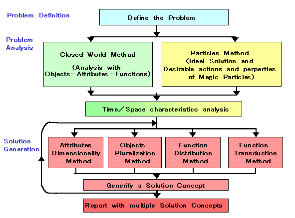
(c) USIT provides a clearly defined simple procedure for applying the methodology. The procedure is composed of three stages, i.e. Problem Definition, Problem Analysis, and Solution Generation, and is illustrated in the flowchart in Fig. 1.
.
Fig. 1 Flowchart of the USIT procedure. (Slightly modified from Sickafus [4])(d) The technological system of the problem is described in clearly-defined terms of Objects, Attributes, and Functions.
(e) Elements of techniques in USIT are simple and well explained in guidelines. Especially, there are only four techniques used for the solution generation, and they are used in correspondence to the concepts of Objects, Attributes, and Functions.
(f) No outside knowledge bases and software tools are used in USIT. Engineers can learn and memorize USIT easily. USIT can be used most effectively in cooperative work of a group of engineers.
(g) Engineering details, such as specifications, figures, numbers, costs, deadlines, etc., are put aside the consideration during the USIT procedure. This choice aims to make the concept generation as freely and widely as possible. The multiple conceptual solutions obtained with USIT should later be reviewed from various engineering and business points of view introducing the above mentioned engineering details. The solutions should be filtered and further developed in such succeeding stages.
The problem solving procedure
with USIT is explained in the following with reference to the flowchart
in Fig. 1. This description is based not only on Sickafus' materials
[3, 4], but also on the two case studies [5, 6] and the experience of a
training seminar on USIT [11] conducted by the present author.
3. Problem Definition Stage in USIT
USIT regards its first stage, i.e. for Problem Definition, very important. In this stage the problem we are going to solve is specified. The success in the application of USIT depends mostly on the degree of appropriateness in the problem definition.
In Figs. 2 and 3, examples (originally
written in OHP sheets) of the output of this stage of USIT are shown.
They come from the two case studies which the present author made during
the USIT Training Seminar conducted under the instruction by Ed Sickafus.
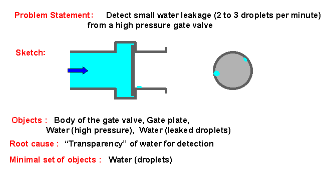
Figure 2 is the problem definition of Case Study A, i.e. "Detecting the
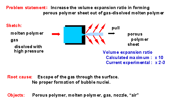
leakage of water from a gate valve", while Fig. 3. is for Case Study B,
"Increase the foam ratio in forming porous plastic sheet".
 |
|
| . |
Fig. 2. Problem definition of USIT Case Study A (Detecting the leakage of water from a gate valve) |
 |
|
| . |
Fig. 3. Problem definition of USIT Case Study B (Increase the foam ratio in forming porous plastic sheet) |
During this stage, the analyzer should describe the followings briefly but clearly (after group discussions):
(a) Problem Statement: The problem to be solved is written in a statement of one or two lines. Goal, task, constraint, etc. should be mentioned briefly.
(b) Sketch: Conceptual sketch of the system for understanding the problem situation.
(c) A list of Objects: To list up the Objects composing the problem system.
(d) Root Cause: To describe the plausible root cause(s) of the problem. One or a few causes.
(e) Minimal Set of Objects: Objects necessary in the minimal focused scope of the problem.
To describe the Problem Statement
(a) may seem simple and easy at the first sight, but is very delicate and
rather difficult because a slight modification of its phrases may change
the whole direction of the problem solving. For example, let us compare
several possible drafts of Problem Statement for the Case A in the following.
- Find a method to detect the leakage of a high-pressure gate valve used in the oil pipeline.
- A high-pressure gate valve to be used in the oil pipeline has been manufactured. Find a method to detect its leakage.
- Find a method to examine the manufacturing precision of the gate plate of a high-pressure gate valve.
- As a process in the manufacturing test, a high-pressure gate valve is to be examined for the leakage by the use of water. Find a leakage detection method.
- As a process in the manufacturing test, a high-pressure gate valve is to be examined for the leakage by the use of water. Find a method to detect the leakage up to 2 to 3 drops per minute.
- As a process in the manufacturing test, a high-pressure gate valve is to be examined for the leakage by the use of water. Find a method to rapidly detect the leakage up to 2 to 3 drops per minute.
- Find a method to rapidly detect a small water leakage up to 2 to 3 drops per minute.
The description of Plausible
Root Cause is also very delicate. The reader should compare the following
drafts for the Case A.
- Because water is transparent and not easily visible by eyes.
- Because the leakage points can not be known beforehand.
- Because the amount of water leakage is small.
- Because water is "transparent", i.e. neutral and insensitive to many detection methods.
The description of Plausible
Root Cause is very useful for the purpose of focusing the problem effectively
and of solving the problem efficiently. The description gives a criterion
to judge whether a solution is "meaningful" or not. Thus, the description
of the Plausible Root Cause works as a bias in interpreting the problem
situations and limits the views into the problem. Because of these
effects and implications, it is of crucial importance to describe the Problem
Statement and Plausible Root Cause appropriately; these descriptions determine
the directions of all the efforts of the problem solving [4].
In USIT it is a principle to focus
our efforts towards "A Single Problem", as discussed above. If the
analyzer feel uncomfortable with the single problem, he/she should clarify
multiple problems in a system and solve such problems one by one with USIT.
4. Problem Analysis Stage in USIT
As shown in the flowchart in Fig. 1, the process with USIT in the Problem Analysis Stage are composed of two paths; the analyzer may use either any one of them or both of them sequentially in any order. The first path is called "Closed-World Method", which starts with the description of the current system in problem. The second path, named "Particles Method", images the ideal solution at first and then try to find the ways to realize it. These two paths merge and then the Uniqueness Analysis should be carried out to reveal the space and time charcteristics of the system.
4-1. Definitions of Basic Terminology in USIT
Let us study the following definitions of basic terminology in USIT [3, 4].
"Objects": described in nouns, exist by themselves, occupy space, and interact with other objects to modify/prevent from modifying their attributes. Examples of Objects: Water, pipe, electron, photon, etc. Examples of non-Objects: hole, heat, electric current, etc. Exceptional Object: "Information" is exceptionally regarded as an Object.
"Attributes": described in class names of adjectives, and are the categories of characteristics of Objects. Examples of Attributes: color, weight, linear expansion rate, etc. Examples of non-Attributes: red color, 30kg, etc. These are the values of Attributes, and called metrics. USIT does not handle with engineering details and hence not with characteristics.
"Functions": described in verbs,
and modify or prevent from modifying the attributes of Objects. Examples
of Functions: to change color, to accelerate, to contain, etc.
In a most general form, a Function has the structure as shown in Fig. 4,
where the Objects A, B, and C may be different or identical.
 |
|
| . |
Fig. 4 Scheme of a Function |
4-2. Problem Analysis Procedure with the Closed-World Method
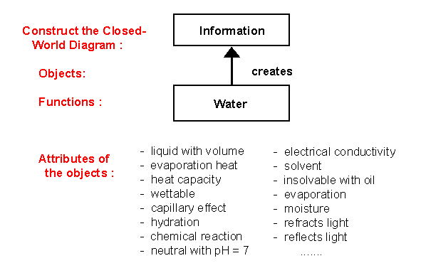
4-2-1. Draw the relationships of Objects and Functions into a Closed-World Diagram
First in the Closed-World Method, the analyzer should clarify the intention in the original design of the current system, with a functional system analysis. For this purpose, a Closed-World Diagram should be constructed with the following rules [3, 4]:
- Only the Minimal Set of Objects defined in the Problem Definition Stage are handled with.
- Select the most important Object (Object A) in the system and set it at the top level.
- Then arrange other Objects B, C, etc. towards the lower levels in accordance to the "favorable functional relationship to the upper Object" (see the definition of this relationship below).
- An Object should not be drawn at multiple places.
- All the Objects should be drawn in the diagram. Any Object which does not fit in the main chain of Objects should either be drawn in a side chain or be eliminated because of no essential role.
- Between the two Objects connected directly, describe the single Function which represent the favorable functional relationship.
In the above rule, two directly
linked Objects (i.e. upper Object A linked with lower Object B with a favorable
functional relationship) must satisfy the following conditions simultaneously:
- B is in a favorable relation with A (i.e., B generates A; B modifies the parameter of B; or B eliminates A).
- B is in physical contact with A, and otherwise B can not perform the function on A.
- In the intention of the original designer, A comes before B. A is more important than B.
- If A is withdrawn, B becomes unnecessary or redundant. A is the main reason for the existence of B.
The Functions in the system need
to be clarified during the close examination of these favorable functional
relationships and only one Function is drawn for each direct vertical link.
The rules described here are rather restrictive. This restriction
aims at clearly understanding the design intention (or the principal functions
to perform as a system).
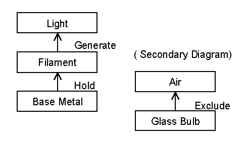
As an example, let us consider the
famous TRIZ textbook problem for finding a light bulb not breakable and
suitable for the robot's exploration on the moon surface. The solution
is "to eliminate the glass bulb". Sickafus has drawn the Closed-World
Diagram of an ordinary electric bulb as shown in Fig. 5, and says the textbook
solution comes up quite naturally from this diagram [4].
 |
|
| . |
Fig. 5. Example of a Closed-World Diagram (Electric bulb) |
For the Case A discussed above, the
Closed-World Diagram for the system of detecting the water drops is drawn
as in Fig. 6. Since "Information" is handled exceptionally as an
Object, the detection system can be represented naturally.
 |
|
| . |
Fig. 6. Example of a Closed-World Diagram (Case Study A) |
4-2-2. Listing up Attributes of the Objects
Next, the analyzer should list up various Attributes of all the Objects drawn in the CW Diagram [see bottom part of Fig. 6]. The main purpose of this step is to widen the scope of consideration. Thus, it is not advisable to restrict the listing of the Attributes only to those clearly relevant to the problem. Attributes which may not seem relevant at first sight might surprise you with its contribution to inventive solutions.
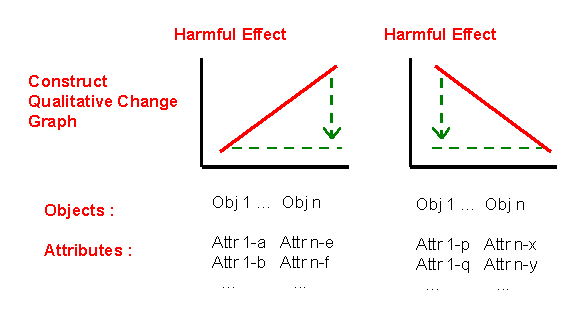
4-2-3. Constructing the "Qualitative Change Graphs" and Classify relevant Attributes
The "Qualitative Change Graphs" are
drawn in the scheme shown in Fig. 7. The graphs show the relation
between the harmful problem effect on the ordinate and some properly selected
Attribute on the abscissa. With the progress of USIT, the intention
of using the QC Graphs seems to have changed. The graphs should now
be understood never qualitatively but roughly and qualitatively.
The slope lines in the right and left graphs may be understood just to
distinguish the increasing/decreasing relationships.
 |
|
| . |
Fig. 7. Scheme of the Qualitative Change Graphs in the Closed-World Diagram Method |
The main task in constructing these graphs is to check the Attributes listed in the preceding step by turns and to select those having increasing or decreasing relationship to the problem effect. Such Attributes are classified into increasing/decreasing relationships and are written down at the bottom of the left/right drawings, respectively. Attributes without increasing/decreasing relationships may be eliminated in this stage. By the use of this classification list, the analyzer can easily understand which Attributes should be changed in which direction. Furthermore, the ordinate may be represented with some target functions (e.g., the detection of the leaking water).
By the use of these "QC Graphs", we may easily find various cases of TRIZ' Technical Contradictions (i.e. the contradiction, where the improvement in one parameter (i.e., Attribute) makes some other parameter worsen).
4-2-4. Object-Attribute-Function (OAF) Statements
The Functions shown in the CW Diagram are stated more clearly in terms of the relevant Objects and Attributes by using the framework of Fig. 4. Then all such statements of Functions are summarized in the form of the "OAF Diagram". This analysis step, however, is rather complicated and may be skipped.
4-3. Problem Analysis with the "Particles Method"
The Particles Method is adopted from Altshuller's Smart Little People Method. It pursues the TRIZ philosophy of thinking of the Ideal Solution first. The method proceeds in the following steps:
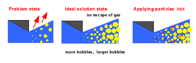
4-3-1. Sketching the Current Problem State
Let us take, as an example, the Case
B problem, i.e. "Increase the foam ratio in forming porous plastic sheet"
[6]. The sketch of the current problem state may be shown in the
left part of Fig. 8. The sketch shows the small part of the system
in enlargement, which is essential to understand the mechanism of the bubble
formation.
 |
|
| . |
Fig. 8. Example of problem analysis with the Particles Method (Case Study B) |
4-3-2. Sketching the Ideal Solution State
In the philosophy of TRIZ, the Ideal Final Solution works perfect, costs nothing, and does NOT exist. Though our solution may not be so ideal like this, we should first think of our Ideal State and just sketch it (see the middle part of Fig. 8). You should not try to depict any means to achieve the Ideal State. You should sketch the result only.
4-3-3. Depict the Particles in the Figure
Next you should compare the sketches of the Current Problem State and of the Ideal State, and depict a number of X Marks at the places of any difference; then regard the X Marks as the "Particles" (see the right part of Fig. 8). (Note: Though not drawn in the figure, you may put X Marks outside the polymer.)
Particles are regarded as "magical substances/Fields having any desirable properties and able to perform any desirable actions" (in the TRIZ terminology, "Fields" are the generic term representing forces, interactions, physical fields, energies, etc.). You should next consider what kind of actions you want these Particles to perform and what kind of properties they should have for doing such actions. The Particles are somewhat magical at first; but you must realize them with some substances and Fields obeying the natural laws at the end. This realization makes the difference from fairly tales.
Israeli researchers renamed Altshuller's "Smart Little People" into "Particles", in order to avoid analyzers' subconscious behavior that would not like to put the People under any severe/hazardous situations. In contrast to the pictures in TRIZ textbooks (especially those for children) where little figures of people are drawn, the X Marks (not even O Marks) in SIT/USIT contribute to more abstract thinking.
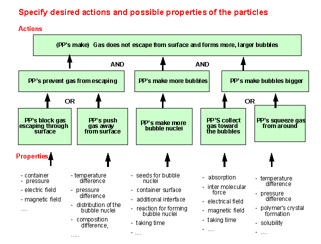
4-3-4. Construct the AND/OR Tree for specifying the actions of Particles
Next you should describe the actions
you want the Particles to perform in a brief statement, and then break
the statement down into elements of actions in a hierarchical way as shown
in the top part of Fig. 9. The top statement essentially corresponds
to the Ideal State rephrased from a picture (in Fig. 8) into words (in
Fig. 9). When you break down the action statement into one lower
level, you should judge whether you need the lower level actions at the
same time (i.e., an AND relation) or you need either one of them (i. e.,
an OR relation); then you should specify such AND/OR relations in the hierarchical
diagram, which Sickafus calls the AND/OR Tree. When you break down
a lower-level action further, you do not need to consider the neighboring
actions.
 |
|
| . |
Fig. 9. Example of specifying the desired actions and properties of the Particles (Case Study B) |
In the action statements, you should not use technical terms but rather use plain everyday words. This is because every technical term has clear technical concepts/images as the background and often restricts the scope of later consideration of the means of realization. For example, in Fig. 9, the phrase "to gather gases into the bubbles" suggests various activities inside the bubbles, whereas the phrase "to squeeze gases from around the bubbles" a variety of activities outside the bubbles (here the word "squeeze" is used in a figurative sense).
4-3-5. Listing up the candidates of properties desirable for the Particles
Below the elemental actions in the AND/OR trees, you should next list up the candidates of properties desirable for the Particles to perform the actions (see the lower part of Fig. 9). In this stage, the properties may be somewhat vague, abstract, and not so selective. In the example in Fig. 9, in order to block the gases at the sheet surface, we are thinking to use a container wall, higher pressure outside the sheet, electrical field to push back the gases (assuming the gases have some electrical charges), etc. These examples illustrate that the Properties used in this step are wider and looser in terminology than the Attributes. Similarly, the Actions are wider in terminology than the Functions.
While listing up these Properties, various tips of ideas for realizing them would come up in your mind. Since they become keys to the conceptual solutions in the next step in USIT, you should remember them and express them briefly in the description of Properties (at the level not too restrictive).
4-4. Analysis of Space and Time Characteristics ("Uniqueness Analysis")
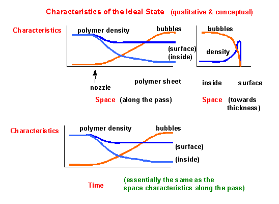
After analyzing with either the Closed-World Method or the Particles Method, you should always carry out the Analysis of Space and Time Characteristics. Taking the (harmful) problem effect (or else the system's performance) as the ordinate, you should express its characteristics with respect to space and time in qualitatively-drawn graphs.
In the present example of Case B
(see Fig. 10), the distance from the slit nozzle was chosen as the abscissa
axis for representing the characteristic space of the system. The
growth of bubbles in number and size is illustrated in the graph, together
with the change in the density of the polymer. Recalling the requirement
of avoiding the escape of gases through the polymer surface, a policy was
chosen not to make bubbles near the surface, and was illustrated in the
graph with different polymer densities betweem near the surface and in
the bulk. In the upper-right part of Fig. 10, the polymer density
is drawn with respect to the distance from the surface; thus the density
difference near the surface and in the bulk is shown more clearly.
(Note: If a different policy is chosen to make the bubbles occur
even near the surface, solutions partially different from the present ones
would be required.)
 |
|
| . |
Fig. 10. Example of space/time characteristics analysis (Case Study B) |
To show the system characteristics with respect to time, a small portion of the polymer was traced from its initial molten state, via the extraction through the nozzle and forming bubbles, and finally to the state as the porous polymer sheet. The curves in the graph are essentially the same as in the space-characteristics graph; but the time-characteristics graph contributes much for the analyzer to recognize the importance of taking time for the bubbles to grow in number and size.
Among the TRIZ techniques, the derivation
and elimination of "Physical Contradictions" are most important.
Physical Contradiction is a conflicting situation where one parameter of
a system is requested to be made in one direction and at the same time
in its reverse direction. When we face with such a contradictory
requirement, we very often think "It's impossible!" Whereas TRIZ
gives us amazing solutions in such a case. TRIZ' solutions are derived
with the Principle of Separation with respect to space, time, or some other
conditions. The space and time characteristics analysis in the "Uniqueness
Analysis" of USIT forms the basis of using this Separation Principles in
TRIZ.
5. Conceptual Solution Generation Stage in USIT
At the third stage of USIT, by using the analysis results obtained so far, the analyzer should generate conceptual solutions to the problem and write a report with multiple solutions. As shown in the flowchart of Fig. 1, the four Solution Generation Techniques and the Generification Technique are repeatedly used to make the solutions wider and deeper.
5-1. Attributes Dimensionality Method
This method focuses and operates on the Attributes of each Object. Sickafus lists up typical means in this technique as follows:
- To activate/deactivate an Attribute.
- To make a fixed Attribute variable or varying, and to make a variable Attribute fixed.
- Convert a space-related Attribute into a time-related Attribute, and vice-visa.
In the case of water leakage
detection, we consider the Attributes of water, i.e. the object to be detected;
to each Attribute listed up in the step of the CW Diagram (see Fig. 6),
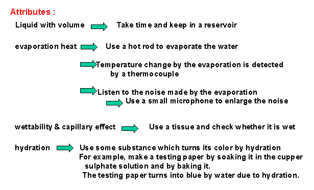
this method is applied successfully as shown in Fig. 11. For example,
the Attribute 'heat of vaporization' reminds us the phenomenon of vaporization;
if we put a heated bar onto water drops, it makes sounds of vaporization,
and we can hear it. Another Attribute 'hydration' (i.e. combining
reaction of water molecules around ions etc.) in the list reminds us an
idea of using a test paper of dried cuppor sulphate, which turns blue by
the combination with water. These ideas are also examples made fruitful
by associative thinking of technologies and phenomena in everyday life.
 |
|
| . |
Fig. 11. Example of solution generation with the Attribute Dimensionality Method (Case Study A) |
5-2. Objects Pluralization Method
When we focus and operate on Objects, we use the method of Pluralization in USIT.
- To multiply an Object, or else to divide an Object into smaller ones.
- To vary the number of Objects from zero (i.e. Trimming) to infinity; the extremes are important.
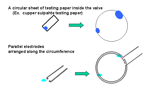
In the case of the water leakage
detection, when we use a method to detect water at one place, we have to
carry out the test around the inner circumference of the valve many times
by turns. So it is worthy of considering how to pluralize the detecting
places. By using the Objects Pluralization Method, we could propose
several methods for detecting the water leakage at every place around the
circumference in parallel at the same time (see Fig. 12).
 |
|
| . |
Fig. 12. Example of solution generation with the Object Pluralization Method (Case Study B) |
5-3. Function Distribution Method
We next focus and operate on the Functions in the system (especially those described in the Closed-World Diagram) in the following way:
- To redistribute the Functions among Objects (including some newly introduced ones) in the system.
- To exchange, modify, overlap, separate, combine, etc the Functions.
5-4.
Function Linkage Method (or Transduction Method)
This method tries to link one Function with another sequentially. When we describe Functions in the scheme of "Attribute --> Function --> Attribute" as shown in Fig. 4, we may link two Functions via a common Attribute into "Attribute --> Function 1 --> Attribute --> Function 2 --> Attribute". The sequential link of Functions achieves some enhanced/new Function.
In the example shown in Fig. 11, this method is used almost unconsciously. For instance, the solution "Touching with a heated bar to evaporate water => Listening the noise during evaporation => Amplifying the noise with a small microphone" is performed with three means linked sequentially.
5-5. Generification of Solution Concepts
In USIT, when you write a solution, you are advised to describe it in general and wider terminology. It comes from USIT's intention that aims not at detailed technical solutions but at more general and creative technological solutions in the conceptual level.
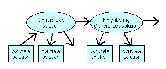
This Generification Method can be
used even more aggressively. With this method, you may develop your
solution concepts in the order as illustrated in Fig. 13. The system
of solutions expressed in this way are named in various ways, such as Road
Map and Mind Mapping. For instance, it was used in an excellent TRIZ
case study published by Ford Motor Co. [7]. Even with this Generification
Method alone you may have much higher creation productivity than with the
Brain Storming Method.
 |
|
| . |
Fig. 13. Scheme of conceptual solution generation with the Generification Method |
5-6. Reporting multiple conceptual solutions
By using the four Solution Generation Methods and the Generification Method repeatedly as illustrated in the flowchart in Fig. 1, you should list up multiple solutions. During this process, you should remember that the four techniques are focusing on Objects, Attributes, and Functions in different ways, and hence you should apply the techniques to the Objects/Attributes/Functions listed up in the analysis stage by turns. And you should summarize the solutions you obtained in the scheme of the road map (see Fig. 13). In this manner you can smoothly systematize and conceptualize multiple solutions; and you should finally write a report of the results obtained with USIT. This concludes the whole procedure of applying the USIT for a problem solving.
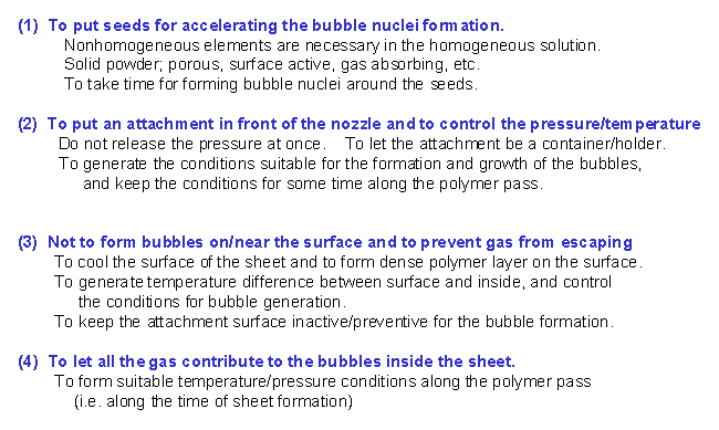
The conceptual solutions obtained
for Case B are demonstrated in Fig. 14. This case was analyzed with
the Particles Method (and not with the Closed World Method). The
ideas of these solutions came out rather naturally (i.e., without using
the four solution generation techniques consciously) and were systematized
smoothly. The AND/OR Tree Diagram describing the actions and properties
desired for the Particles (in Fig. 8) is a hierarchical description of
the Ideal State in a top-down manner, and hence is close to the road-map
representation. Consequently, when we consider the listed items of
Actions and Properties by turns and add ideas of realizing them technically,
the conceptual solutions can be obtained in a systematic way.
 |
|
| . |
Fig. 14. Example of generated conceptual solutions with USIT (Case Study B) |
6. Evaluation of USIT through Practices and Ways of Introducing USIT
Ford Motor Co. has developed and practiced USIT intensively. They have published their activities, philosophies, and outputs in [8, 9]. The present author attended at the USIT Training Seminar conducted by Dr. Ed Sickafus of Ford, and produced for himself the two case studies described above during the three days [10]. Later in Japan, he led four cases of problem solving with USIT in Company A, and conducted a three-day USIT Training Seminar [11] in Company B, where four real industrial problems were solved with USIT.
Through these practices, the present author is evaluating USIT as follows:
- Terminology, concepts, techniques, and processes of USIT are defined clearly and are easy to learn.
- The whole USIT procedure is clearly shown in a flowchart, compact without redundancy or useless part, and effective in application.
- The Particles Method is very easy to apply even for the beginners. It may be an effective way to apply USIT by using the Particles Method as its core technique.
- The Closed World Method needs some training to master. It forms the basis of the four Solution Generation Techniques; hence it is desirable to understand and apply the method as the principal analysis method in USIT.
- For the four Solution Generation Techniques, it is necessary to learn a number of cases of good applications and to clarify the ways of thinking with these techniques.
- Actually applying USIT to practical industrial problems, we could smoothly obtain high-quality solution concepts.
- After applying USIT, we should expand/enhance and examine the conceptual solutions more closely from the technological view points. In this stage, knowledge bases and software tools of TRIZ may be used effectively.
- USIT expert(s) and engineers group should work together for solving problems effectively and deeply. USIT is suitable for such a group work.
- Learning the Ford activities as the model case, USIT experts should be brought up inside companies as the core team for introducing the USIT and TRIZ methodologies.
In conclusion, the present author
highly recommends the USIT methodology, as it succeeds the essence of TRIZ
and is a clear, concise, and practical method for creative conceptual solution
to actual industrial problems. It is the easiest way to apply the
essence of TRIZ. The study and experience of TRIZ would be fully
used during the application of USIT.
In closing this paper, the present
author wishes to express his sincere thanks to Dr. Ed Sickafus, the developer
of USIT, for his kind guidance and continuing encouragement.
References:
[1]
'TRIZ Home Page in Japan', Editor: Toru Nakagawa, URL: http://www.osaka-gu.ac.jp/php/nakagawa/TRIZ/eTRIZ/
(in Japanese and in English)
[2]"Let's
Learn 'TRIZ'! -- A Methodology for Creative Problem Solving", Toru
Nakagawa, Plant Engineers, Vol. 31 (August, 1999), pp. 30-39 (in Japanese);
in 'TRIZ Home Page in Japan', Oct. 1999 (in English).
[3]
"Unified Structured Inventive Thinking: How to Invent", Ed. N. Sickafus,
NTELLECK, Grosse Ile, Michigan, 1997, p. 488.
[4]
"USIT Training Seminar (USIT-01) Course Material", Ed. N. Sickafus, NTELLECK,
Mar. 1999.
[5]"USIT
Case Study (1) Detection of Small Water Leakage from a Gate Valve",
Toru Nakagawa, 'TRIZ Home Page in Japan', Jul. 1999 (in Japanese), Aug.
1999 (in English).
[6]"USIT
Case Study (2) Increase the Foam Ratio in Forming a Porous Sheet from Gas-solved
Molten Polymer", Toru Nakagawa, 'TRIZ Home Page in Japan', Jul. 1999
(in Japanese), Aug 1999 (in English).
[7]"Windshield/Backlight
Molding -- Squeak and "Buzz" Project -- TRIZ Case Study",
Michael Lynch, Benjamin Saltsman, Colin Young, American Supplier Institute
Total Product Development Symposium, Dearborn, Michigan, Nov. 5, 1997;
The TRIZ Journal, Dec. 1997.
[8] "A
Rationale for Adopting SIT into a Corporate Training Program", Ed Sickafus,
TRIZCON99: First Symposium on TRIZ Methodology and Application, Novi, Michigan,
Mar. 7-9, 1999.
[9]"Injecting
Creative Thinking into Product Flow", Ed Sickafus, 4th Annual International
TPD Symposium - TRIZ Conference, Industry Hills, California, Nov. 17-19,
1998.
[10]
"USIT Training Seminar (Mar. 10-12, 1999, Detroit) (Instructor: Dr. Ed
Sickafus): Participation Report", Toru Nakagawa, 'TRIZ Home Page in
Japan', Mar. 1999 (in Japanese and in English)
[11] "USIT
Training Seminar in Japan: First Trial in a Company", Toru Nakagawa,
'TRIZ Home Page in Japan', Sept. 1999 (in Japanese and in English)
| Top | 1. Introduction | 3. Problem Definition Stage | 4. Problem Analysis Stage | 5. Conceptual Solution Generation Stage | 6.Evaluation of USIT | References |
| Top of this page | Let's Learn TRIZ! | USIT Case Study (A) | USIT Case Study (B) | USIT Seminar by Sickafus | USIT Training Seminar in Japan (1) | USIT Training Seminar in Japan (2) | Japanese
page |
| Home Page | New Information | Introduction to TRIZ | TRIZ References | TRIZ Links |
| TRIZ News & Activities | TRIZ Software Tools | TRIZ Papers and Tech Reports | TRIZ Forum |
Last updated on Apr. 24, 2000. Access point: Editor: nakagawa@utc.osaka-gu.ac.jp